Top 10 Real Flying Saucer Aircraft

There is undoubtedly a certain fascination with UFOs of the alien variety. While my personal view is that the whole concept was a fabulous disinformation campaign, delivered through the USAF Project Blue Book, there is a community that strongly believes that Earth has been repeatedly visited by alien entities and flying saucers.
For American readers, I am aware that all of us foreigners are aliens, and creatures from other worlds are referred to as ‘space aliens’. As this usage is, like their curious reversed dates (the month preceding the day), their irrational hatred of the letter ‘U’, an inability to pronounce the name ‘Craig’ and some other aberrations, confined to the USA, I will ignore it. If you are American, for ‘alien’, read ‘space alien’
Sadly, for the UFO community, this article is not about alien-flown UFOs, but aircraft featuring (broadly) a wing with either a circular, or an annular, planform. There are a surprising number of these, and quite a few have even been flown. In coming up with a top 10 selection, I have been biased towards those that did actually become airborne, but have also been attracted to those which either feature purity of form, or alternatively are so spectacular that they cannot be ignored. Of course, in a list of ten, readers’ favourites will have been left out, or put in the ‘wrong’ place. The selection and ordering of aircraft in any Top Ten list is always going to be subjective, so I accept responsibility, but make no apology for my choices
Aerodynamics
Before launching into our list, I feel I should say a word about the aerodynamics of circular-winged aircraft. If you are in search of a quick fix you may jump straight into the top 10 below; for those wishing to know more, I’d like to explain a little about the aerodynamics of the flying saucer, mainly because having a circular wing is largely such a bad idea. The issues I will raise may not be insuperable, but their impacts do have an influence on the configuration, control and performance of circular and annular winged aircraft.
The most obvious problem is going to be the lift-dependent drag of the aircraft. Lift–dependent drag is the drag caused by the generation of lift. There’s no such thing as a free lunch in aerodynamics and if you order a bigger portion you’re going to get a bigger bill (unlike in nouveau cuisine where the inverse occurs). This is proportional to lift squared, divided by aspect ratio (a measure of the slenderness of the wing as viewed from above or below). The larger the aspect ratio, the smaller the lift-dependent drag at a given lift. This is why sailplanes have long slender wings, and for low-speed aircraft, high aspect ratio is a good indicator of efficiency.
For a circular wing, the Aspect Ratio is 4/Pi, or about 1.27. An equilateral triangle has an aspect ratio of about 2.31, and a typical modern airliner will have an aspect ratio around 10.0 or more. So circular wings are inefficient.
A second impact of having a low aspect ratio is that the lift curve slope is low. This slope is the amount of lift generated per degree of angle to the airflow. As a generalisation, a circular wing will require about twice the angle to the airflow to generate the same lift as a high aspect ratio wing of the same area. So, in addition to having high lift dependent drag, we can expect our circular wings, at low speed, to have high angle of incidence, to need high power, and, perhaps to have significant forward visibility issues.
Stability and Control
What of stability and control? Well, one issue is going to be to have sufficient control power. Because of the compact nature of a circular wing, the arm available for rear-mounted control surfaces is likely to be relatively small, compared to the conventional rear-fuselage-mounted tail surfaces.
From a longitudinal stability point of view, care will be required, for a non-spinning circular configuration, to manage the longitudinal stability. If the centre of gravity is at the point of radial symmetry, the configuration will be longitudinally unstable, because the centre of lift will, at subsonic speeds, be ahead of this. For simple light aircraft applications, the centre of gravity will generally be designed to avoid this issue, for example by having a forward located engine. For radially symmetric designs, low speed stability is likely to be significant problem, unless the whole airframe is spun, like a frisbee, so that a combination of angular momentum and gyroscopic precession provides a measure of longitudinal stability.
From the lateral perspective, there is no reason to anticipate that a flying disc at low incidence would be anything but neutrally stable. However, at the relatively high incidences which might be required for take-off and landing, it is probable that vortices would be shed from the highly swept outer wing leading edge, which would be destabilising in both pitch and yaw, hence requiring some form of fin, rudder and aileron control.
Annular Wings
Annular wings, in the form of a disc with a circular hole in the centre, have also proven a popular form for innovators. From an aerodynamic perspective, these may be thought of as a pair of wings in tandem, joined at the tips. Because the rear part of the wing sits within the downwash field of the front part, it will experience a lower aerodynamic incidence, which does have the advantage that an annular winged aircraft will generally naturally pitch nose down at the stall. Otherwise, the aerodynamic qualities are likely to be similar to those of a circular wing.
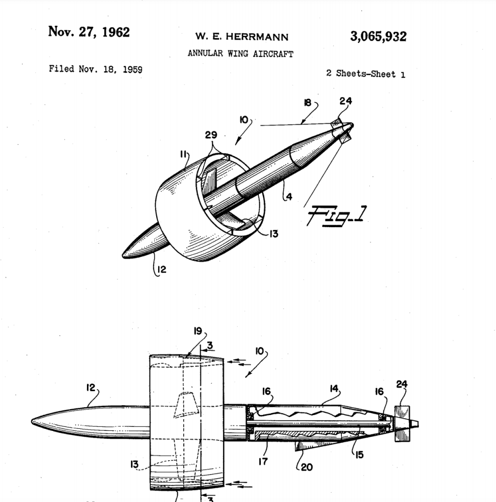
For a given diameter, an annular wing will have less area than a circular wing, and would be likely to have a more complex and heavier structure. However, other considerations, such as the view on landing, and possibly somewhat higher lift curve slope and lower lift dependent drag might prove advantageous. That said, the flows around an annular wing could well be interesting and highly dependent on yaw as well as pitch, assuming the near streamwise edges at the wing tips, and at the outer portion of the central aperture, all shed vortices at high incidence.
Spinning discs
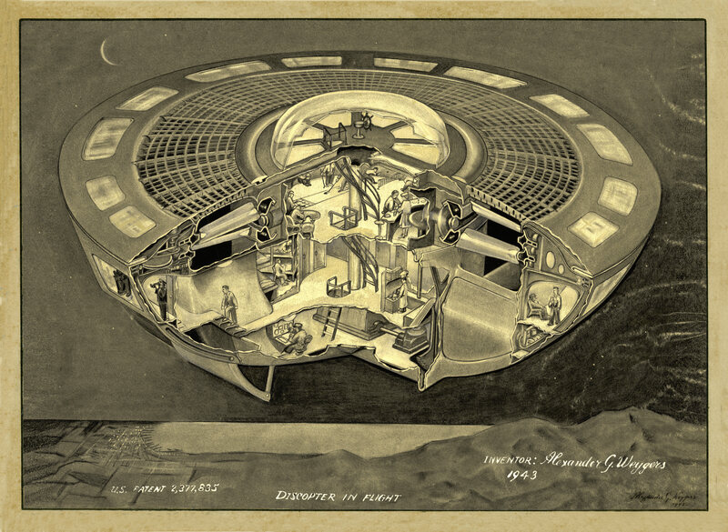
What about spinning discs? Well, evidently, frisbees can glide for significant distances, and are relatively stable in flight, so why not a spinning disc? Well, maybe in an unmanned application, but a human pilot is going to need to be facing more-or less in the direction of flight, and maintaining that with a spinning wing is going to be difficult. Not impossible (see helicopters for example), but certainly complex and heavier than not spinning the wing.
An interesting aspect of spinning discs is that necessarily, the centre of gravity also will be the centre of rotation, to ensure the device is rotationally balanced. The implication of this is that spinning discs are aerodynamically unstable at subsonic speeds, when the centre of lift will be ahead of the centre of gravity. The nose-up pitching moment which results is, however, converted through gyroscopic precession into an oscillation in roll, and moreover this is itself stabilised by the rotational inertia of the spinning disc.
Control of a spinning wing will also be difficult as both gyroscopic precession, and differential lift on the advancing and retreating side of the wing is going to complicate any control system markedly – again, see helicopters.
Are there benefits?
Clearly proponents of circular-wing designs have been able to persuade investors and governments to part with significant resources to construct and fly a surprising variety of designs. Given the disadvantages, difficulties and complications I have highlighted, what might be the sales pitch? We have seen that circular wings have a low aspect ratio and a low lift curve slope. As a consequence, a circular-winged configuration will give you a lot of wing area for a given span, and, provided you can manage the forward visibility of flying an approach at fairly high incidence, slow approach and landing speeds. Further, a low wing span for a given area should result in a relatively light structural design, as wing root bending moment will be reduced. These characteristics might have some attraction for carrier-based operations, especially if the need for a folding wing can be avoided.
In principle, manoeuvre performance could be quite good, as long as one is considering roll rate and instantaneous turn rate, that is. Both of these should be good, firstly due to low roll inertia because of reduced wing span, and secondly due to large wing area and high stalling incidence. Sustained turn rate, however, is likely to be horrible due to high lift-dependent drag.
Have any supersonic disc-wings been built? Well, there are rumours that this might have occurred. I am quite sceptical about these because wave drag could be quite high unless an Aerospike or extended fuselage nose were used to keep the aircraft bow shock away from the wing leading edge.
“But what about supersonic flying saucers?”, I hear the true believers cry. Well, I am a sceptic, principally on propulsion grounds. I can see that rotation could manage some of the stability issues, in principle at least, but I can’t resolve how sufficient thrust could be delivered to propel a spinning disc at supersonic speeds, or how such a vehicle could be crewed and controlled. But then, I don’t have access to alien technologies or knowledge.
With this introduction in place, and if we’re all sitting comfortably, let’s begin?
Lee-Richards Annular Biplane and Monoplane
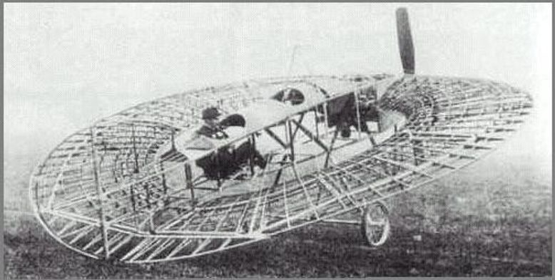
The Lee-Richards Annular Biplane and Monoplane appears first in this list, in recognition not only of the early date of these pioneering aircraft (1911 – 1914), but also because of the development programme which eventually led to the relatively successful Annular Monoplane.The Annular Biplane was developed from a prototype built by G J A Kitchen, who had patented the concept of an annular winged aircraft. The prototype, and the patent were both purchased by Cedric Lee, who then, with George Tilghman Richards, set about developing it for flight trials. In 1911, the completed aircraft, with a 50 hp Gnome engine, was taken to Famine Point at Heynsham for trials, which have been described as “not particularly satisfactory” [British Aircraft 1809-1914, Peter Lewis, 1962].
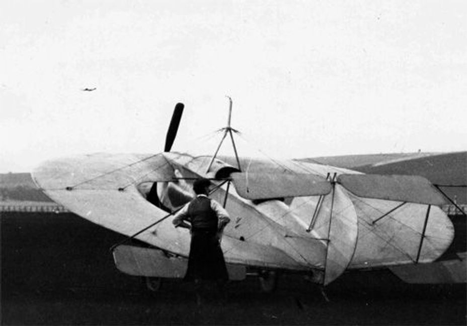
It remains unclear whether powered flights were successfully completed by this machine, which was destroyed when its hangar was blown down in a gale on 4th-5th November 1911. Other accounts suggest the aircraft was only flown as a glider.
Some readers may either have noted its appearance in the early part of the film ‘Those Magnificent Men in their Flying Machines’ or have come across the non-flying replica built for that movie, which is now with the Newark Air Museum. The replica has small ailerons mounted on the interplane struts, twin rudders, and an elevator attached to the trailing edge of the upper wing.
Perhaps the real significance of the Lee-Richards Annular Biplane was the demonstration that wings of this planform could form the basis of a flying machine. Following the loss of the biplane, Lee and Richards conducted a detailed programme of experimentation and research, including experiments with model gliders, and a year later were flying a Sesquiplane glider at Kirby Lonsdale. This aircraft featured a circular lower wing and a crescent-shaped upper wing.
Additionally, in what may well have been a first in the UK, wind tunnel tests were made at East London College and in the National Physical Laboratory, which showed the wing as continuing to produce lift at incidences of up to 30 degrees, with a gentle stall.
With this encouragement, a thoroughly convincing annular-winged monoplane was designed, and built at Shoreham. This aircraft flew successfully on 23 November 1913, although handling was plainly initially somewhat difficult. Again, accounts differ somewhat, but it is clear that the aircraft crashed and was re-built at least twice, with modifications introduced to improve elevator control.
Over the three versions of the aircraft, a total of 128 hours was flown, and the developed aircraft was said to be easy to fly and control, and able to take off with full load at only 30 mph. Maximum speed was 85 mph, landing speed 45 mph, and endurance 3 ½ hours, all creditable figures for a 1914 aircraft with an 80 hp engine. Wingspan was only 22 ft for an aircraft weighing 1680 lb when fully loaded, and the aspect ratio was 1.72.
The initial aircraft was followed by orders for two more, which were, in April 1914, being built for the Gordon Bennett air race. It is likely that these aircraft would not have been completed due to the outbreak of the First World War in July 1914, but the original aircraft continued flying up to September 1914.
Strong Points: The transition from the biplane to the monoplane design seems to have been well researched, and as a result, the monoplane was substantially successful, delivering good performance for an early aircraft, along slow take-off and landing speeds.
Weak Points: It is uncertain whether the biplane ever flew. The monoplane underwent a range of modifications to reduce stability and increase controllability.
Our interview with a SR-71 pilot here

The Hush-Kit Book of Warplanes will feature the finest cuts from Hush-Kit along with exclusive new articles, explosive photography and gorgeous bespoke illustrations. Order The Hush-Kit Book of Warplanes here. Save the Hush-Kit blog. If you’ve enjoyed an article you can donate here. Your donations keep this going. Thank you. Order The Hush-Kit Book of Warplanes here
9. Feast Circle CW
The Feast Circle appears at number 9 in this list, primarily to show that the pioneering spirit of Lee and Richards is alive and well, and living in Australia.
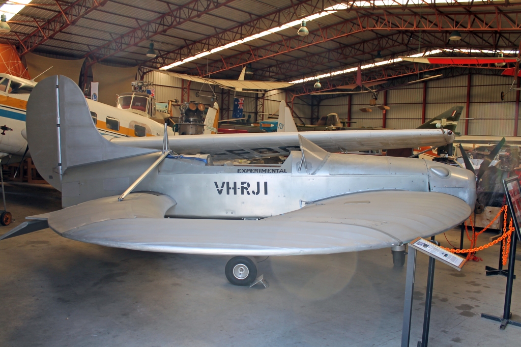
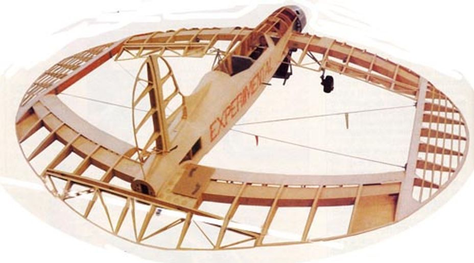
The Feast Circle is an aircraft very much in the spirit of the Lee-Richards monoplane. Following experiments by Ron J Feast using a series of flying models, a small annular wing single-seat aircraft of wood and fabric construction was designed and built, starting in 1997, and making its first flight in July 2001. Where the Lee-Richards aircraft used an 80 hp Gnome engine, the CW used an 80 hp Rotax. The exterior of the wing planform was circular, but the interior featured a straight line at the tip, no doubt making the wing easier to construct, but also something of a joined-wing design, with curved front and rear wings joined by the tip pieces.
As might be expected, while the aircraft proved able to fly quite successfully, it had a very slow landing speed. Elevators were fitted to the trailing edge of the rear wing, and ailerons to the trailing edge of the front wing, and lateral control at the low landing speed proved to be difficult, leading to a number of modifications.

These included a change to a tricycle undercarriage, and a fairly drastic revision of the wing planform, with the rear wing being moved forward, shorter tip pieces being fitted to accommodate the new rear wing position, and dihedral being introduced. Both the ailerons and the elevators were also substantially increased in area. Interestingly, the Lee-Richards monoplane had also been modified to reduce its excessive stability, and had larger control surfaces fitted as well.
The aircraft was successfully flown in its new configuration in 2005, but, by January 2009, had been donated to a museum. Nevertheless, it’s a remarkable achievement in the modern regulatory environment to fly such an unconventional aircraft, and have it registered by the airworthiness authorities, hence my decision to include the CW in this list.
Strong points: A recent and successful attempt to build and fly an annular winged aircraft.
Weak points: As might be expected, the usual problems of stability and control, particularly at slow speed. Performance might not have been all that sparkling either, but nevertheless able to deliver a low take-off and landing speed.
8. Nemeth Roundwing
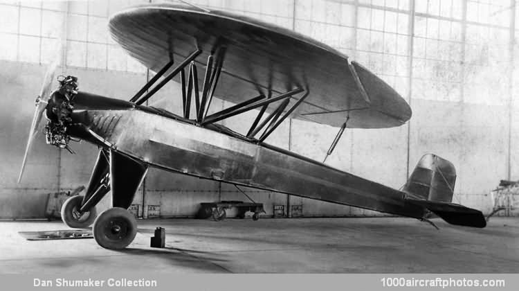
The Nemeth Roundwing is the first circular-winged aircraft appearing in this list. The aircraft, as appears to have been the case for many of this type, was developed following initial trials with flying models built by its designer, Steven Paul Nemeth.
These trials led to a large model of the aircraft being tested in the wind tunnel at University of Michigan in 1929, with encouraging results, which in turn resulted in the development of a full-size aircraft, the Nemeth Roundwing, also known as the Umbrellaplane.
In its initial form, the aircraft was based on the lengthened fuselage of an Alliance Argo light aircraft, and was powered by a 90 hp Lambert engine. The 16 ft diameter circular wing was mounted above the fuselage in a parasol position, and the fuselage retained the empennage of the Alliance aircraft. The rear part of the wing featured a split flap, and the outer part of the wing trailing edge carried the ailerons. Construction of the aircraft was completed in 1934, and was carried out as a student project at the University of Miami. One cannot but feel some envy at this opportunity for the students.
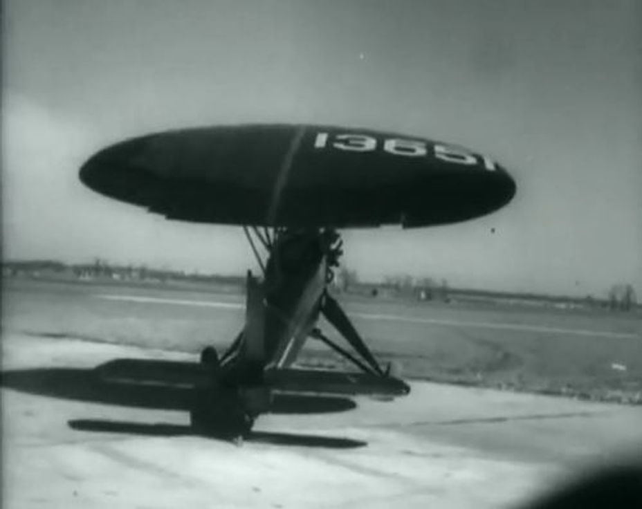
The aircraft flew successfully, but was significantly modified over the next two years. A more powerful Warner Scarab engine of 120 hp was fitted, and the wing trailing edge was significantly refined. Photographs of the later version of the aircraft show Youngman-like flaps and ailerons have been fitted. These have a significant gap between the wing and the control surface/flap, which would greatly improve effectiveness, allowing flight at very low speeds. Maintaining the tailplane of the original aircraft would be vital to allow the aircraft to be trimmed because the flaps would produce a significant pitching moment when deployed.
Given the 125 hp engine, the high lift devices, and the aerodynamic characteristics of the circular wing, it is not surprising that extremely short take-off and landing distances of 63 ft and 25 ft have been quoted. The aircraft was said to be incapable of stalling and easy to fly, with a landing speed of 30 mph. The aircraft does have a notable high ground angle, and this is presumed to have been used to allow landings to be made at high incidence and low speed.
Strong Points: Flew successfully, and was easy to control. Looks fun, and a great student project.
Weak points: Required a fuselage and tailplane to deliver stability and control, so although disc-winged, not really a flying saucer..
7. Snyder ARUP
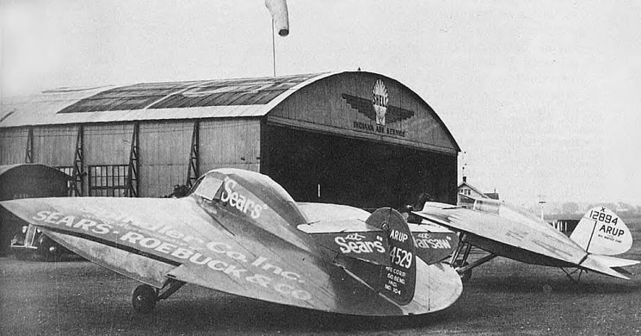
The Snyder ARUP was an attempt to create an easy-to-fly aircraft for the masses – a popular theme that appears to have been doomed to failure at every attempt. The attraction of using a very low aspect ratio wing for this purpose reflects what we have observed with all these light aircraft projects. With a large wing area, and the ability to fly at very low speeds, the prospect appears at hand of an aircraft which is both easy to fly and able to operate from small fields. Combined with a small span, making the aircraft easy and cheap to store when not in use, the attraction seems obvious. ARUP was selected as a name for the aircraft from a contraction of ‘Air Up’ – a reflection of an intent to produce a plane for the masses.
In the case of the ARUP, development by Snyder, assisted by Raoul Hoffmann, followed the usual pattern of balsa wood models, followed by development of a glider, and then fitting a small motor to the glider. As a powered aircraft, the initial S-1 design did fly, but was not a great success, proving to be difficult to control.
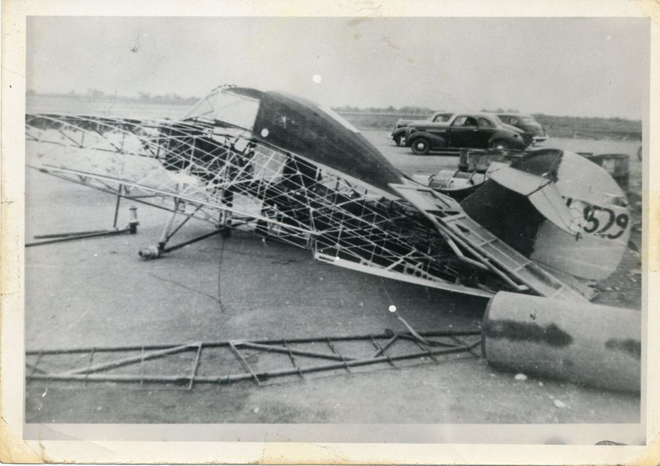
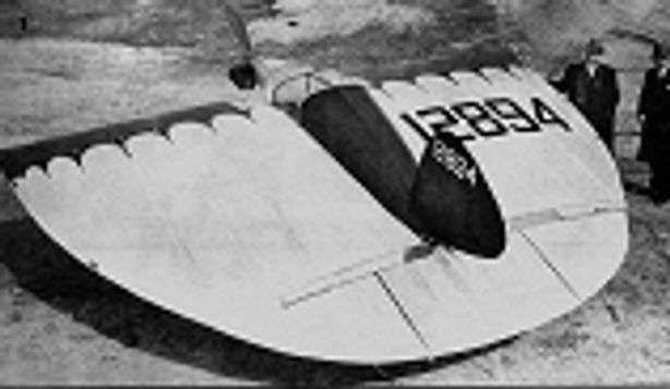
Nevertheless, the results were sufficiently encouraging to lead to the development of three further aircraft, the ARUP S-2, S-3 and S-4. The S-2 flew for the first time in 1933, and was a small single-seater with a half-moon shaped wing, with straight leading edge and rounded training edge. Control was achieved using trailing edge elevons, operated together for elevator control, and in opposition for roll control, for which they were supplemented by small ailerons at the wing tips.
The S-2 flew well and was widely demonstrated across the US, both in air-shows and to both NASA and the US Army. The S-2 could be flown at up to 35 deg incidence without stalling.
It is worth commenting that the ability, shared by all these low aspect ratio aircraft, to take-off and land very slowly becomes of less consequence once they are constrained to operate from the hard surfaces of current runways. It is very easy to land at 30 mph directly into a head wind, but a significant crosswind on a narrow fixed runway could result in drift angles approaching 45 deg, leading either to a tricky landing on the runway, or perhaps a deliberate and slow off-piste landing elsewhere on the airfield.
The S-3 variant of the aircraft made one flight only before being destroyed by a fire, thought to be the result of arson. The S-4 was very similar to the S-2 and S-3, the main differences being a cleaner cockpit enclosure and the use of larger ailerons at the trailing edge of the outer wing, and a fin-mounted tailplane and elevator. The S-4 first flew in 1935, and remained in use until the Second World War.
Strong points: A practical aircraft, successfully developed and demonstrated over a number of years
Weak Points: Control system changes over time suggest that the ability to approach and land at low speed is a positive, but also that control power at low speed was an issue.
6. David Rowe UFO
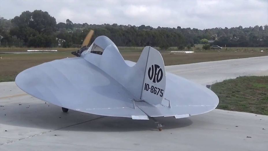
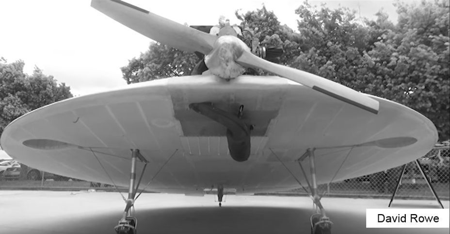
The David Rowe UFO (Useless Flying Object) earns its place on this list as a modern example of a light aircraft with a circular wing. Like the previous examples, the UFO started life in model form and was then developed through a series of prototypes, with revisions to power, centre of gravity, undercarriage and controls. The exercise appears to have been driven more by a belief that it could be done, rather than by an ambition to produce a production design.
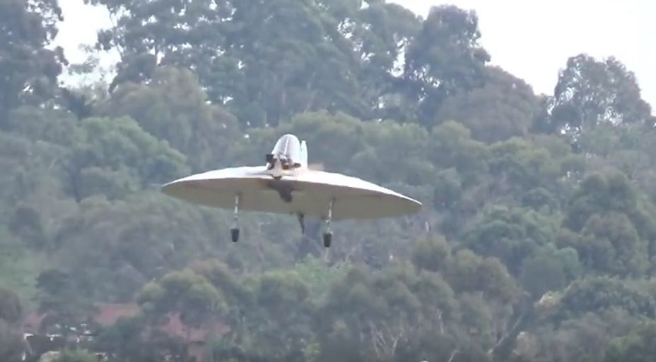
The first ‘full-size’ aircraft was the Rowe Wild Thing, which was registered in 1995, powered by a 28 hp Cuyuna snowmobile engine. With this engine, the Wild Thing proved to be under-powered, and the next development was the Rotax-powered UFO. This proved relatively successful, although a little tail heavy, leading to further design revisions to produce the UFO-3.
The UFO-3 used a different wing section, and featured a re-positioned cockpit and engine, resulting in an improved aircraft which was flown for 13 years, commencing in 2000. By any measure, this aircraft must be considered a success, although an attempt to create a two-seat version had to be abandoned when entry to the aircraft was found to be too difficult, perhaps reminding one unfairly of the reputed Boscombe down comment on the Blackburn Botha “Entry to this aircraft is extremely difficult – it should have been made impossible”.
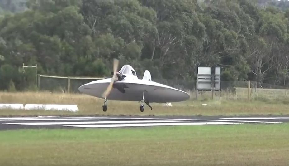
The latest aircraft in the series is another single-seater with a tail-wheel manually retractable undercarriage. This aircraft can be seen flying in the attached video clip
The UFO earns its place in this list because of its original design, its evident enduring success, and the sense of fun involved in creating a one-man UFO for the entertainment of both the pilot and ground observers.
Strong points: What’s not to like. The UFO manages to be cute, fun and a successful design, all at the same time
Weak Points: OK, getting into it by crawling along under the wing is perhaps a little undignified; I’m guessing, but it seems likely that a sustained steep turn might involve a bit of height loss.
5. Astro V Dynafan
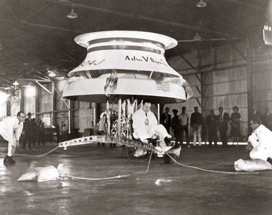
And now for something completely different, the Astro V Dynafan. One of the reasons for including the Dynafan in this list is because it uses a completely different approach to the generation of lift.
The Dynafan seeks to exploit the Coanda effect. What is the Coanda effect? Well, that august body of learning, Wikipedia, provides this definition:
“The Coandă effect (/ˈkwɑːndə/ or) is the tendency of a fluid jet to stay attached to a convex surface. It is named after Romanian inventor Henri Coandă, who described it as “the tendency of a jet of fluid emerging from an orifice to follow an adjacent flat or curved surface and to entrain fluid from the surroundings so that a region of lower pressure develops.”
So, if you blow a jet of high velocity air across a convex surface, not only will the jet curve to follow the surface, but air will be entrained to flow over that surface as well, causing a region of low pressure to develop. In the Astro Kinetics Corporation’s Dynafan, a Chevrolet Corvair engine was used to drive a 2-bladed propeller which pushed air through a converging duct so that it passed over the aerofoil-profiled ring below the duct.“
The circular jet not only generated lift from the aerofoil, but also entrained (sucked along with itself) more air, helping to generate additional lift. The whole device was radially symmetric, and was demonstrated in tethered flight in San Antonio on December 16, 1964, making 9 successful ‘flights’ in front of an audience of 200 people.
Great things were expected of the Dynafan, claimed by its manufacturers as easy to scale up, and cheap to build – a production 2-seat version could be available for the cost of a family car, and the demonstration model was said to be designed to fly for 150 miles, and be capable of 86 mph.
However, the real target of the Dynafan was the helicopter market, where its simplicity of design and construction were claimed to lead to drastically reduced production and operating costs compared to complex rotorcraft. Skycrane-type heavy lift operations were viewed as an ideal application, and the company’s press release claimed a 100ft diameter Dynafan would be capable of lifting a 250,000 lb payload.
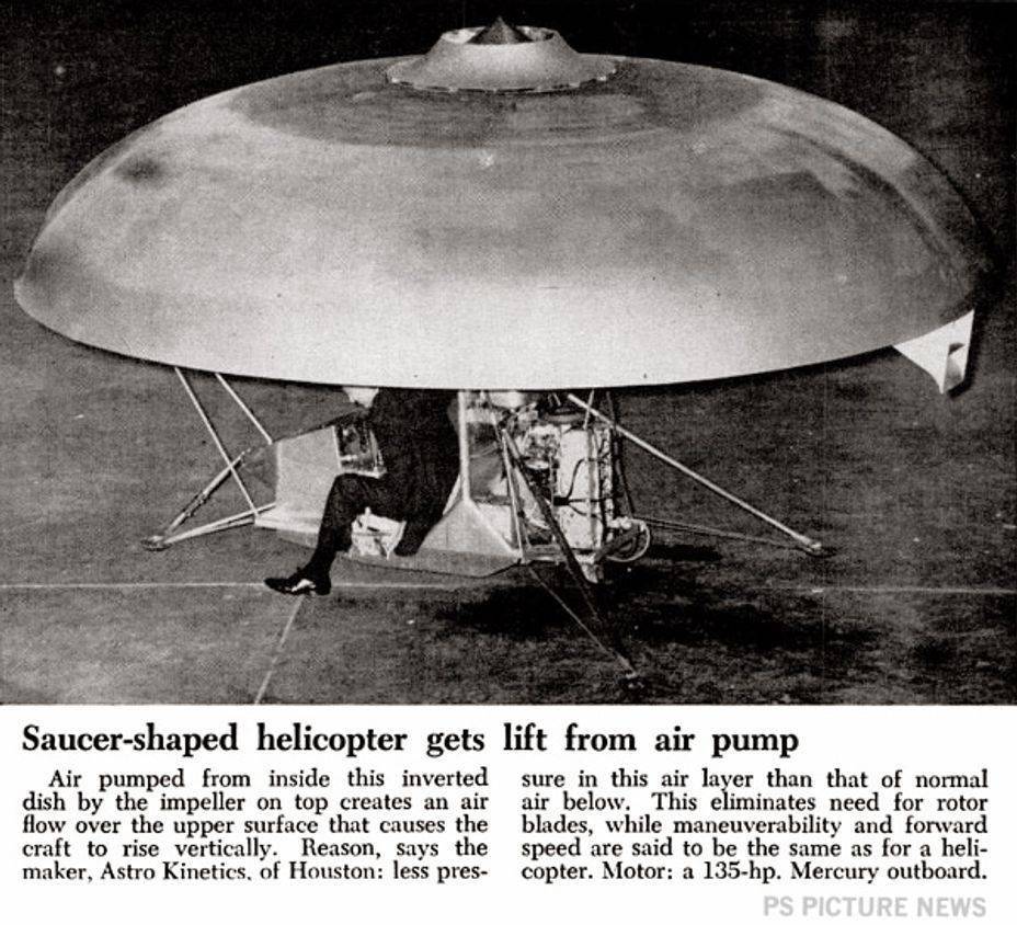
Control of the Dynafan appears to have been achieved by varying power to the motor, and by the use of four small flaps to vary the width of the slot, at the front and rear to control pitch, and on either side for Roll. Torque was to be balanced, and yaw controlled, through the use of four small surfaces positioned in the jet flow.
It is unclear whether un-tethered flight was attempted or achieved by the Dynafan.
Strong points: A combination of the Coanda effect and an ejector-augmentor propulsion/lift system; demonstrated to be able to perform a tethered hover; very ambitious scale-up plans
Weak Points: To contrast the aphorism about aircraft that look good being good – ‘If it looks like a lash up maybe it won’t work’. The control system looks rudimentary, and it’s likely that the small ‘rudders’ on the outside of the lower ring would have been inadequate to control torque. The control system shows no signs of considering gyroscopic effects.
4. Couzinet RC-360 Aerodyne
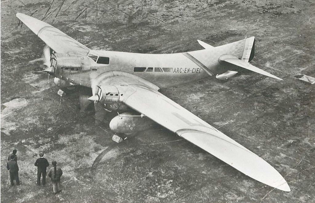
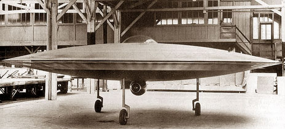
The Couzinet RC-360 has been chosen for this list as it is, perhaps, the purest instance of man-made ‘flying saucer’; because it raises some interesting technical questions; and because it provides an opportunity to showcase one of the 30s prettiest airliners, the Couzinet ‘Arc en Ciel’ (Rainbow).
Photo Arc en Ciel
In January 1933, this elegant aircraft crossed the South Atlantic from Senegal to Natal, Brazil in 14 ½ hours, as part of a notable flight linking Paris and Buenos Aires. This flight led to a regular postal service across the South Atlantic commencing in 1934.
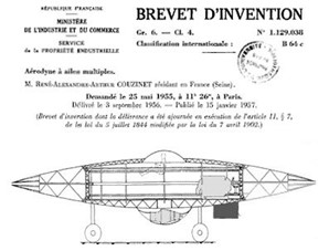
In 1955, Couzinet began a project to build a vertical take-off aircraft, the Aerodyne and registers a patent for it on May 25, 1955, number 1.129.038 and titled “Aerodyne with multiple wings”, patent which will be published in 1957, after his death. A non-flying 60% scale model of the Aerodyne is built and shown to the press.
Photos of the RC-360
The concept was a small radially symmetric craft, featuring a pair of contra rotating discs surrounding a stationary cockpit, each disc carrying 96 small wings on its circumference. The winged discs were enclosed in a fairing, and were to be powered by three pairs of Lycoming engines. In addition, a small turbojet was added to provide horizontal thrust.
In the end, the full-size Aerodyne was never completed and never flew. So why is it of interest? Well, apart from its fabulous appearance, the use of contra-rotating spinning discs poses interesting questions about control.
The spinning discs are proposed for a good reason. By having a pair of discs rotating in different directions, the torque required to drive the discs can be balanced out, providing the means of stopping rotation of the aircraft. The same approach is used in the Kamov series of helicopters to dispense with the need for a tail rotor.
How would controlled flight be achieved? In yaw, this would be easy, as small differences in power to the discs can be used. But control in pitch and roll is another question, due to a physical effect called gyroscopic precession. This is a fairly familiar phenomena which has the result that a force applied to a rotating object produces a response at 90 degrees to the applied force.
Suppose you wish to pitch a helicopter. What you do is apply cyclic controls so that the lift on one side of the disc is increased, and decreased on the other. Because of gyroscopic precession, the rotor will not roll, but will respond in pitch.
Now consider a force trying to pitch the Aerodyne. For example, because the centre of gravity is behind the centre of lift, the result for a non-spinning disk would be a nose up pitching moment. For one spinning disc, the actual outcome would be a rolling moment, but for two discs spinning in opposite directions, two rolling moments in opposite directions would be generated, resulting in no disturbance in pitch or roll.
Which is fine, but does raise the question of how the Aerodyne would be controlled?
A question which fortunately never arose, because it never flew.
Strong points: The purest and most futuristic looking flying saucer, somehow with a touch of French élan
Weak Points: Never built at full-scale and never flown. Unclear how a control system could have been successfully developed.
3. Vought V 173
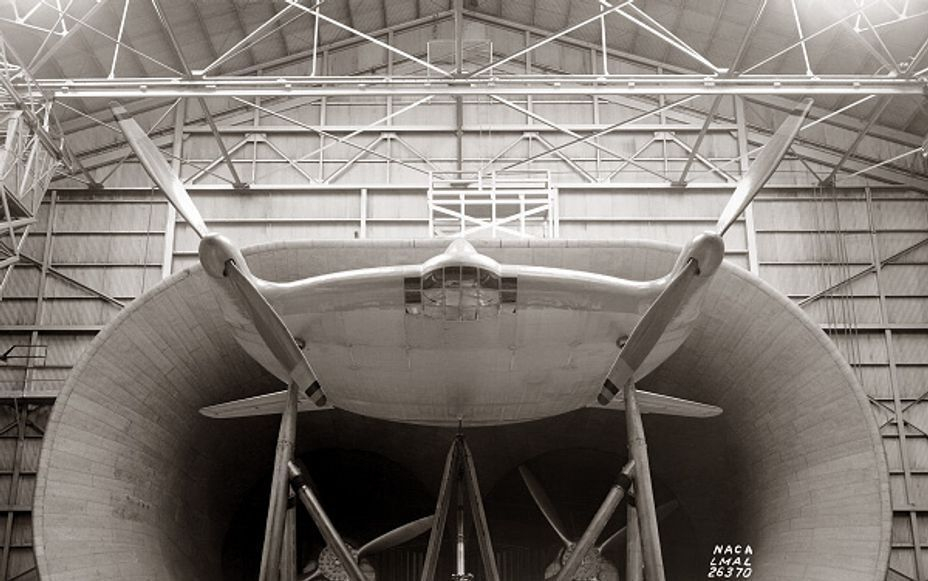
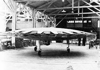
The Vought V 173 arose as a result of US Navy interest in the ideas of Charles H. Zimmerman, who, possibly influenced by having witnessed demonstration flights of the Snyder ARUP aircraft, became interested in possible applications for “discoidal” aircraft i.e. aircraft which, like the ARUP, featured very low aspect ratio wings.One of the characteristics of this type of aircraft is its ability to fly at slow speeds, a characteristic which might prove useful for a carrier-based aircraft. Zimmerman conducted trials at NASA Langley (then the Langley Memorial Aeronautical Laboratory) in 1935 showing that low aspect ratio discoidal wings could generate maximum lift coefficients of 1.8 at about 40 degrees incidence.
In 1937, Zimmerman left Langley, having been employed by Vought Aircraft, a move which facilitated development of his ideas following the normal path of testing flying scale models. In turn, this led to interest from the US Navy, more wind tunnel testing, and the construction of a proof-of-concept aircraft, the Vought V 173. US Navy interest had been sparked by the events at Pearl Harbour, which had confirmed the importance of aircraft carriers to the US Navy, and suggested that a very compact and STOL fighter might allow operation from merchant vessels, and would also allow aircraft to be carried in greater numbers.
The V 173 was an extraordinary-looking aircraft. Not content with merely adopting a low aspect ratio wing like that of the ARUP, the V 173 also featured large diameter propellers positioned at the extreme wing tips, bathing the entire lifting surface in propwash, helping to ensure controllability down to very low flying speeds.
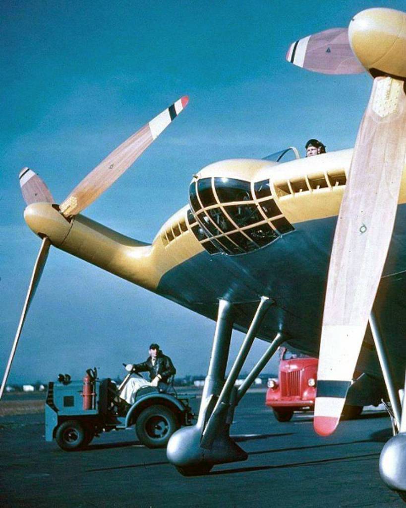
As a consequence of the low lift curve slope, the aircraft would need to fly at significant incidence when approaching to land, and accordingly, the V 173 featured an extraordinarily tall undercarriage, giving a resting ground angle of 22 degrees, which also provided ground clearance for the large 16 ft 6 in diameter propellers. To provide an adequate view, the pilot was located at the extreme front of the aircraft, and the underside of the nose of the aircraft was made transparent to facilitate the view ahead when landing.
Aircraft control was facilitated by twin fins and rudders placed in line with the propellers, tailplanes with control surfaces attached to the rear of the wing, and a pair of moveable control surfaces located at the trailing edge of the wing.
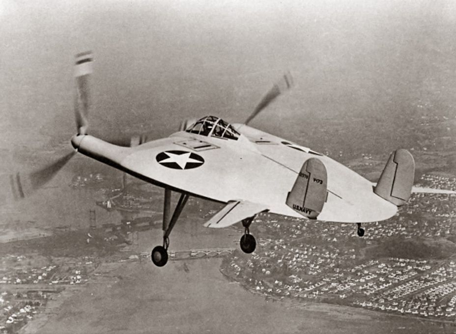
Testing of the aircraft was somewhat delayed because of vibration in the propulsion system – each of the propellers was driven through a long shaft and a gearbox transferring power from the engines. Eventually, however, the aircraft flew on 23 November 1942, with no major problems encountered, apart from high control forces. The aircraft demonstrated extremely short take-off and landing characteristics, with a typical take off run of 200 ft, and a landing after its first flight of 50 ft.
The aircraft completed its flight test programme through 1942 and ’43, eventually making its last flight at the end of March 1947. By this time, it had made 190 flights totalling 131.8 hours, and had caused a bit of a sensation amongst those who assumed they were seeing a bright yellow UFO over Connecticut.
Strong points: Outstanding appearance; Numerous flights; Amazing ground angle
Weak points: Heavy controls; low power; high drag; vibration problems in drive train
2. Vought XF5U-1
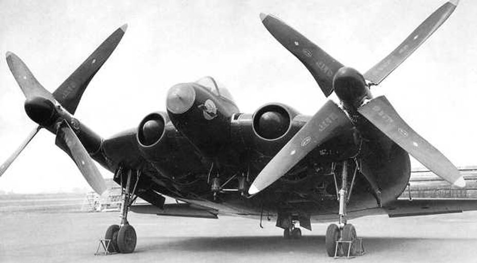
The Vought XF5U-1 makes second place on this list mainly because of the audacious leap of faith by the US Navy and Vought in going for such a radical scale up from the V 173 proof of concept aircraft, particularly when the concept demonstrator had done little, other than to demonstrate the slow landing capability of the configuration, and its marginal controllability.
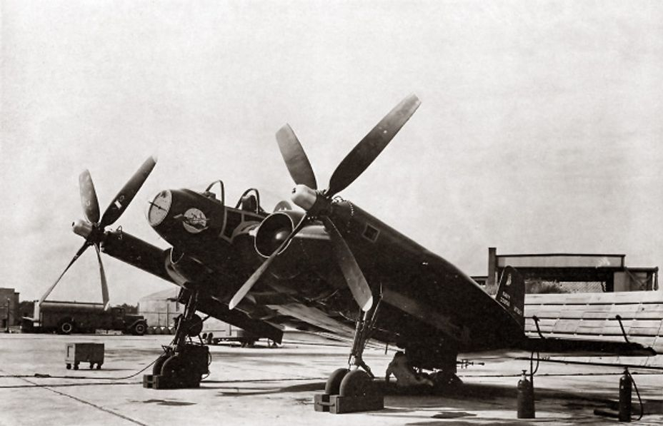
But, hey, the US Navy was reaching out towards an aircraft it hoped would fly at 500 mph and land in a very small space. So, the Vought XF5U-1 was developed in the form of one structural test article and one flyable prototype. The main differences from the demonstrator aircraft were the weight (about 5 times heavier), and the installed power – two 1400 hp P&W R2000 radial engines as opposed to two 80 hp Continental engines. The airframe to be propelled by this 17.5 to 1 increase in power was similar in size to the lightweight wooden demonstrator, just 2 feet longer and with 4ft greater span.
The look of the prototype, dressed up in USN Blue, with its enormous, helicopter rotor-like flapping propellers, was aggressive and startling, with its low aspect ratio wing and 18 degree ground angle. Interestingly, the published three-view drawings indicate that the aircraft could not take-off or land with the fuselage horizontal – the propeller blades would have struck the ground.
What could go wrong? Well, in the end, the rapid advance of jet aircraft technologies and the end of the Second World War probably had as much to do with the demise of this high-risk, low payoff venture as anything else. By the end of the programme, in March 1947, jet engine aircraft were coming into US Navy service, and even had the aircraft flown successfully and delivered its projected performance, it would have been uncompetitive as a fighter.
It seems unlikely that the aircraft ever flew. Even though reference is made to short hops in the very poor Wikipedia article on the aircraft, this seems unlikely to have occurred. In the ground testing that was conducted, there appears to have been significant vibration issues with the propeller drive system. The use of propellers with flapping blades, and generally complex and immature shaft drive would represent significant risk areas for the project.
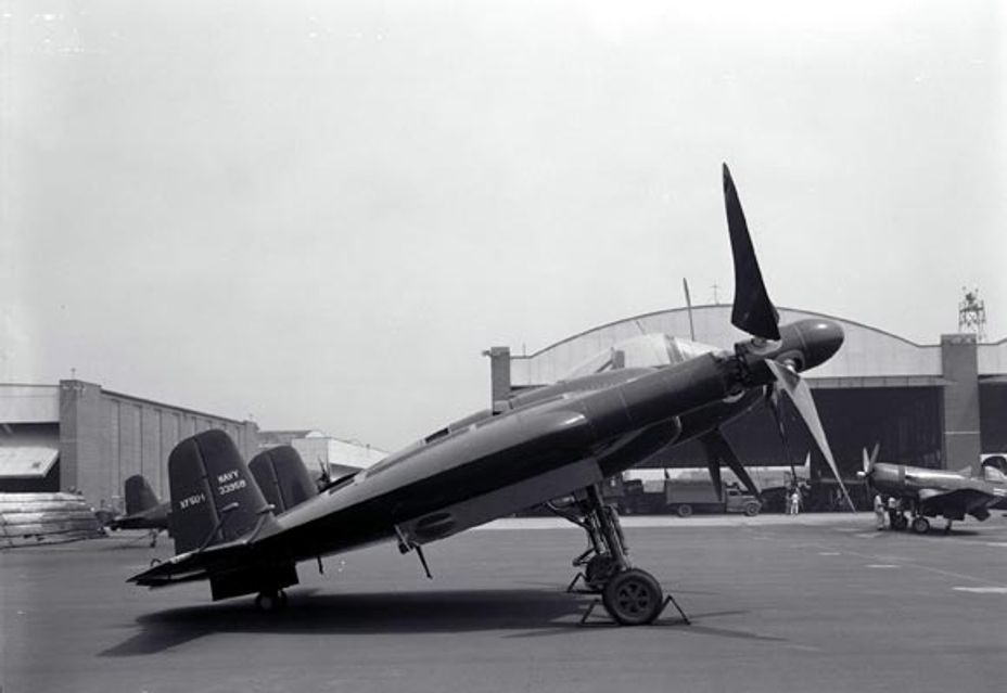
But the look is fabulous, and the ambition colossal, so I make no apologies for placing this bold but unsuccessful design at number two in my list.
This link, buried deep in the otherwise useless Wikipedia article, provides what appears to be a credible, detailed and realistic version of the V 173 and XF5U-1 story, including a first-hand account of the first flight of the V-173.
Strong points: Fearsome appearance; Ambitious and aspirational.
Weak Points: Where were the Risk team on this one? The demonstrator had shown poor performance, likelihood of vibration problems and possible control issues. So we’ll add flapping propeller blades for a bit more fun.
- Avro VZ-9-AV Avrocar
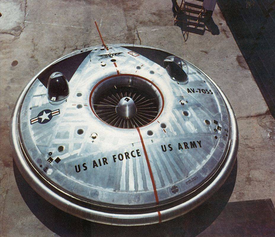
The Avro Avrocar comes in at number 1 on my list for three reasons. Firstly, the purity of the concept in the popular image of a flying saucer is perhaps only matched by the impractical and unsuccessful Couzinet CP-360. Secondly, the grand vision for the whole concept of producing a supersonic weapon system, designed to be stable at supersonic speed, and to manage the inevitable instability at subsonic speeds. And thirdly, the magnificent disconnect between the initial intentions and what was finally achieved.
The project started out with the ambitious objective of producing a VTOL fighter aircraft which could take off vertically, transition to forward flight, accelerate to supersonic speed, and transition back to a vertical landing. The project was developed within a Special Projects Group at Avro, and funded initially by the USAF. Early objectives included an ability to reach a speed of Mach 3.5 at 100,000 ft.
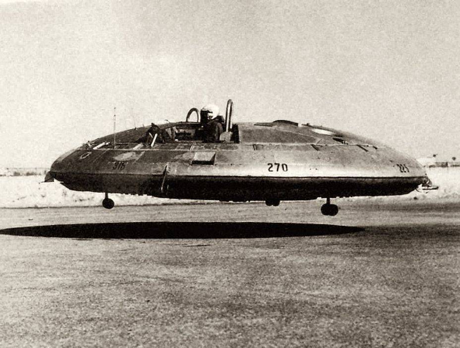
The design was to be powered by a novel propulsion system, and ground testing of this proved somewhat difficult and dangerous, raising questions about the viability of the design. Out of this uncertainty emerged the Avrocar as a small proof-of-concept demonstrator that could both establish the viability of the propulsion system and demonstrate that satisfactory stability and control could be attained. At the same time, the demonstrator could serve as a prototype to meet a US Army requirement for a ‘Flying Jeep’. While the requirements for this were quite modest (25 mile range with a 1000 lb payload, for example), the projected performance was far higher, with a 130 mile range projected with the same payload, and a maximum speed of 225 kt.
The key element of the Avrocar was its Turborotor engine, located at the centre of the radially symmetric craft. Three Continental J69 engines were arranged so that their exhausts drove a 124 blade turbo rotor – a turbine attached to the outside of a fan which pulled air through a central intake, distributing it downwards to provide lift, and radially to provide a control system. The control system involved using the Coanda effect to assist in redirecting the radial jet through the use of a circular ring-like surface immersed in the jet. An interesting aspect of the design was the exploitation of the gyroscopic forces generated by the large Turborotor to assist in stabilising the craft.
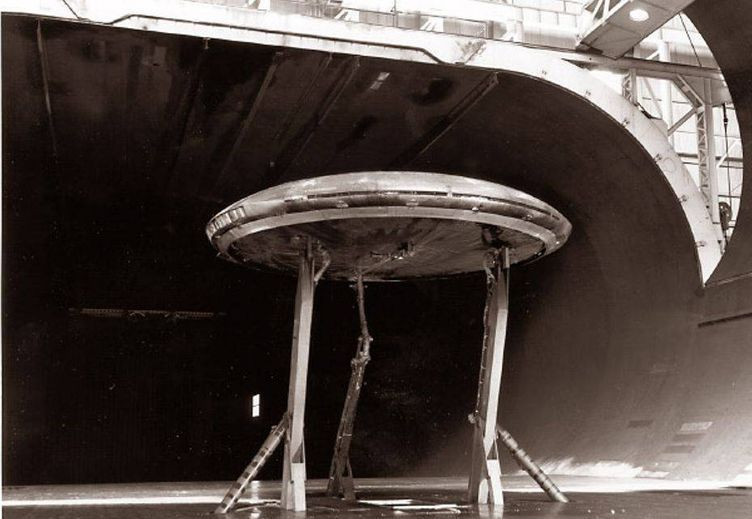
Naturally, in subsonic flight, the Avrocar was aerodynamically unstable because the centre of gravity, at the centre of the circular craft, was behind the centre of lift. However, the spinning Turborotor provided a degree of gyroscopic stabilisation, rather in the manner of a frisbee. However, a combination of the aerodynamic forces and gyroscopic precession resulted in a periodic oscillation in pitch and roll called ‘hubcapping’, which proved difficult to manage, and was never entirely resolved.
Two Avrocars were built, and flight trials revealed a series of problems. Apart from ‘hubcapping’, operation of the Avrocar at relatively low speeds, close to the ground, made it vulnerable to hot gas ingestion, which reduced thrust, and the control system did not have sufficient authority to control the unstable aircraft in horizontal flight.
In the end, this remarkable design could not be described as a success. Although a horizontal speed of 100 kt was eventually demonstrated, the Avrocar proved incapable of operation out of ground effect. Paradoxically, had a rubber skirt been added at an early stage, to contain the ground cushion generated by the Turborotor, Avro would have been in a good position to have invented the hovercraft, in parallel to the Saunders-Roe SRN-1, which also ‘flew’ for the first time in 1959
Strong Points: Radially symmetric flying saucer configuration; Novel propulsion system
Weak Points: Unstable, with unresolved control problems. Unable to achieve flight out of ground effect.
Jim Smith had significant technical roles in the development of the UK’s leading military aviation programmes from ASRAAM and Nimrod, to the JSF and Eurofighter Typhoon. He was also Britain’s technical liaison to the British Embassy in Washington, covering several projects including the Advanced Tactical Fighter contest. His latest book is available here.
And…the ADIFO
The Hush-Kit Book of Warplanes will feature the finest cuts from Hush-Kit along with exclusive new articles, explosive photography and gorgeous bespoke illustrations. Order The Hush-Kit Book of Warplanes here. Save the Hush-Kit blog. If you’ve enjoyed an article you can donate here. Your donations keep this going. Thank you. Order The Hush-Kit Book of Warplanes here

Great analysis and beautifully written. One nerdy helicopter-specific criticism.
Jim says in the context of the Couzinet device and referring to helicopters: “What you do is apply cyclic controls so that the lift on one side of the disc is increased, and decreased on the other. Because of gyroscopic precession, the rotor will not roll, but will respond in pitch.” Whilst the 90 degree delay from input to response is correct, it’s not actually caused by gyroscopic precession.
Helicopter control cannot be unpicked from dynamics, so this explanation will probably cause some glazed eyes … A rotor blade with a flapping hinge close to the hub acts like a mass, spring, damper (or second order system). The mass is the mass of the blade. If it flaps up or down, the restoring moment increases with the displacement. This is a spring.
If the blade is moving upwards, there is an apparent change in wind direction that tend to oppose the motion. The amount of the resistance depends on the rate at which the blade is moving up and down. This is a damper.
Like a pendulum, there will be a natural frequency, which happens to coincide with the angular rate at which the blade is rotating around the hub. When cyclic pitch is applied, the lift force on the blade varies an a frequency of once per revolution (that is at the same rate as the blade is rotating).
We now have a second order (mass – spring – damper) system being ‘forced’ at its natural frequency. It is a fundamental characteristic of such a system that is forced at its natural frequency, that the phase of the response is always 90 degrees, and this is what is responsible for the 90 lag, which mimics gyroscopic precession, but actually has a different cause.
Ah! The complexities of the helicopter … that make it all so interesting.
I should also add, of course, that in the case of the Couzinet device, one is actually talking about gyroscopic precession and Jim’s discussion of that is entirely correct.
One glaring flaw of the Dynafan is that if the engine stops then so does the lift. It can’t glide or auto-rotate so it drops like a stone. If that happens a few feet above the ground then it’s survivable. If it happens at high altitude then the pilot has time to bail out and descend by parachute. If it happens anywhere in between, then it’s certain death.
Why all the hassle with these? I built a free flight one. https://www.youtube.com/watch?v=V06s-FGKBd8
No stability issues if it uses a reflex aerofoil.
Thank you for writing this! Understanding the aerodynamics of these ‘impossible’ shapes is very enlightening. I have a feeling the latest ‘tictac’ UFO videos are an evolution of the USAF ‘lifting body’ research program of the 1960s.
I like eggs.
C´mon guys….you speak about flying saucers but you say nothing about the romanian scientist Henri Coanda and his patents about ´´aerodina lenticulara´´ …?
https://www.go4it.ro/curiozitati/dosare-3998600/proiectele-necunoscute-ale-lui-henri-coanda-7057481/ozn-ul-lui-coanda-fascinanta-creatie-care-a-inlemnit-america-7099030/
I only found a romanian site with informations about the Coanda flying saucer but google translate can help and the pictures with images from his original patents should give you a clue..
..
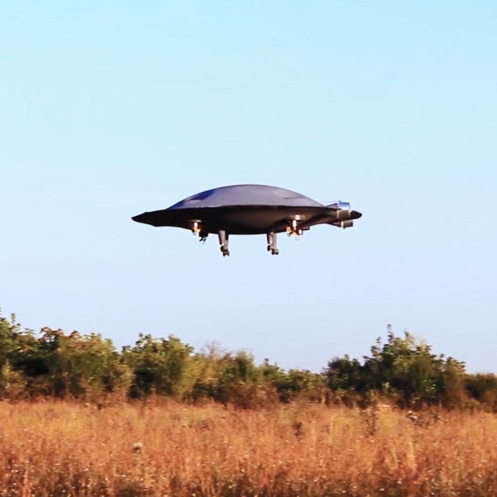
and…ADIFO…just at the end? …really?? Guys, the romanian project ADIFO is THE ONLY FLYING SAUCER THAT ACTUALY CAN FLY ! The model has proven that allready…
Fly-by wire and modern computers can smooth things out I hope.
Don’t forget these:
http://www.astronautix.com/b/bonosaucer.html
Super-STOL is always sought after, especially when airfields and long runways are vulnerable or rare, or for forward / road / rough-field, or shipboard deployment.
The V-173 came about because Zimmerman, while working for NACA, was on the team that saw the Arup S-2 put on an amazing performance.
The S-2 was stall-proof, capable of 45 degree climb (780+lbs, 37 HP engine)
Zimmerman was working towards a VTOL tail-sitter, and chose the Arup’s stall-proof, very high _A_ super-slow flight as the starting point.
His affectation for the outward-turning, plane-changing, tuned, oversized props is somewhat of a mystery, as neither the V-173 nor the XF5U (if it had worked) had enough power nor appropriate landing gear to allow it.
NASA tunnel tests with the V-173 showed that it did not gain anything in performance nor particularly change anything in performance or handling, versus normal sized props for 80 HP engines spinning the other way. (“Radical Wings and Wind Tunnels” book)
It got it’s stall-proof, super-STOL handling solely from the very low aspect-ratio planform.
Aspect ratio is span ^2 / area. At under 3, when flown at very high _A_ very slowly, the wing-tip vortices wrap around, capturing a “bubble” of low pressure above/behind it. Zimmerman adopted the specific aspect-ration because it maximized the effect, allowing super-slow flight. At the same time the vortices trap flow from the front over the top of the wing, keeping it from separating. The wing does not stall, as in the flow stays on top and the controls at the trailing edge always have strong smooth flow.
Zimmerman wrote about this “parachute lift” effect, and also Barnaby Wainfan wrote about it for NASA when they showed interest in his “FMX-4 “Facetmobile, which was very-low aspect-ratio, stall-proof.
The extreme drag of the huge strong vortices are not a burden that a very-low aspect-ratio wing always carries around, supposedly adding to aa highly draggy planform as most writers assume.
The parachute lift effect and drag are elective and temporary.
The Arup planes were sleek and quick on little power, and the Nemeth was faster than the original, stall-proof. Like the Arup, capable of 45 degree climb and 60 degree super-slow descent.
Facetmobile got 100 kts on 40 hp with 340lbs useful load, could stay aloft at <16 kts.
The thrown heel-lift story of the Arup is almost surely fictional. Very many designers were working on very-low aspect-ratio. (A heel-lift out of the box is not shaped or balanced remotely like a wing of the Arup.) It's unreasonable to assume such an outlandish story when there was so much international attention to very-low aspect-ratio.
The Nemeth was developed at the same time, so also the simultaneous Payen/Aubrun AP-10 which apparently flew entirely successfully. See also the Farman 1020: like the Nemeth built on the fuselage of a successful conventional plane (monoplane Farman 400 series). Like the Nemeth faster than the original, stall-proof.
See US patent 1887411 R.B. Johnson for a circular wing plane. (integral wing/body)
See the 1940s Eshelman (commonly called "flying flounder"). Stall-proof, super-STOL, aspect ratio <1. 156 kts on 110 hp
1918 Stout "Batwing" flew entirely successfully, though had essentially zero view for the pilot on landing. First US cantilever monoplane, first with all wood veneer skin.
The German interest in the Sack circular wing was surely part of this international interest. Reportedly Messerschmitt was to be tasked with a reported Me-600 fighter. The Sack AS-6 did not need more power or as much as it had. Probably needed landing gear that allowed more _A_ for taking off into parachute lift.
1934 Moskalyev proposed SAM-4 "Sigma" plane to go as fast as possible, as close to Mach speed as possible. Aspect ratio <1 curved ogival delta wing, two buried V-10 driving contra-props. In the 40s, reportedly in response to US successes with very low-aspect-ratio, he built the SAM-9 test plane with flew successfully, but wasn't followed up with a supersonic jet or rocket powered version.
Also in the '30s, Piana Canova worked on P.C. 100 and 500 gliders, P.C. 140 and other proposed very-low aspect-ratio monoplanes. Also see the "Rosenfelder flying wings" which included tailed and tail-plane-les finned nearly circular wings.
In the late '50s early '60s, Avro Canada and the USAF were working on the Avrocar as the rough-field VTOL half of the circular wing "Weapons System 606a". Simultaneously the Soviet "Sukhanov Discoplan" circular wing gliders were working towards a STOL supersonic fighter. (2 gliders are in museums now).
See also the 1940s Boeing model 390 and 391 "flapjack" carrier-borne fighter proposals. A more close copy of the Arup (very like the Rosenfelder). They dispensed with Zimmerman's overly complex wing-tip props. 390 used a buried two-row 14 cylinder radial. The 391 was proposed with the 4-row 28 cylinder "corncob" radials driving nose contra-props. Reportedly, the exhaust from the supercharger was through a rocket-like outlet that provided thrust, and the cooling air was also taken there, to be accelerated out for extra thrust (cooling air is always just a drag. The 4-row radials had cooling and overheating and fire problems in anything they were mounted in; since this made use of the cooling air, maybe it could have avoided this.)
I picture something the size of the Avenger or S-2, with normal shoulder mounted engines like the S-2, as a "flapjack" attack or ASW plane.
Sergei Sikorsky worked on the Vought/Zimmerman planes, worked on jet powered planes of similar planform and they probably would have outperformed the P-80/F-86 and anything else for the next decade.
It's always said that the advent of the jet age helped kill the Zimmerman "Flapjacks", but it did not need the props situated as they were or props at all, and the US used piston/prop combat planes into the '70s, for support until the '80s, and still uses props.